
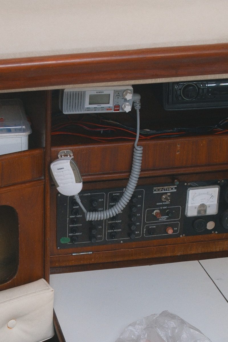
Marine 12V DC electrical systems operate under rigorous environmental and physical constraints. High-humidity, saline environments accelerate galvanic and electrochemical corrosion, while mechanical vibration constantly stresses physical connections. Because 12V systems run at a low nominal voltage, even minor increases in circuit resistance yield catastrophic percentage-wise voltage drops, resulting in equipment malfunction or localized thermal runaway. Modernizing these systems requires strict adherence to physical laws, engineering standards (such as the American Boat and Yacht Council, or ABYC), and systematic diagnostic protocols to ensure reliability, safety, and efficiency.
1. Marine DC Electrical System Topology and First-Principle Physics
The fundamental physics governing marine 12V DC networks rest on Ohm’s Law ($V = I times R$) and Joule’s Law ($P = I^2 times R$). Because the nominal voltage is low, a mere 0.6V drop represents a 5% loss in system voltage, which can cause sensitive marine electronics to reboot or fail. ABYC E-11 standards mandate a maximum allowable voltage drop of 3% for critical safety loads (such as bilge pumps, navigation lights, and VHF radios) and 10% for non-critical loads (such as cabin lighting and convenience outlets). Designers must calculate conductor cross-sectional area based on the round-trip circuit length (positive and negative runs combined) rather than the physical distance to the load.
Conductor material selection is critical to combat the elevated resistance caused by environmental degradation. Marine-grade conductors must be constructed of stranded, tin-plated copper conforming to ASTM B172 Class K specifications. Unplated copper exposed to humid, saline air rapidly oxidizes to copper oxide ($CuO$), which is highly resistive. The tin plating provides a sacrificial barrier against oxidation, while high-strand counts (such as Type 3 stranding) ensure the conductor can withstand continuous structural flexing and engine-induced vibration without undergoing work hardening and subsequent mechanical fatigue.
Unlike automotive applications that utilize the steel chassis as a common ground return path, marine vessels require a fully insulated, two-wire DC system. The use of a metal hull or engine block as a current-carrying conductor is strictly prohibited because it introduces stray currents directly into the marine environment, accelerating underwater metal destruction via electrolysis. Every DC circuit must have a dedicated, insulated negative return conductor routed back to a common negative busbar, which is ultimately referenced to the vessel’s main engine negative terminal or central grounding point.
Contact resistance at terminal interfaces is a primary source of localized heat generation and circuit failure. Every crimp, screw terminal, and busbar interface introduces an interface resistance ($R_{contact}$). If a terminal develops a resistance of only 0.05 ohms under a 30-ampere load, Joule’s Law dictates that the interface will dissipate 45 watts of thermal energy ($30^2 times 0.05$). This localized heat can melt insulation, destroy terminal blocks, and initiate electrical fires long before the circuit’s overcurrent protection device (OCPD) detects an overcurrent condition.
The electrochemical characteristics of the battery bank dictate the dynamic behavior of the entire DC system. Traditional flooded lead-acid (FLA), absorbed glass mat (AGM), and lithium iron phosphate (LiFePO4) chemistries exhibit vastly different internal resistances ($Ri$), discharge curves, and charge acceptance rates. Under heavy loads, such as windlass or engine cranking operations, the battery’s internal resistance causes a momentary voltage sag ($V{terminal} = V_{open_circuit} – I times R_i$). Accurately diagnosing and upgrading a marine DC system requires matching the charging profiles and overcurrent protection to these specific chemical and physical characteristics.
2. Diagnostic Methodologies for Direct Current Fault Isolation
Diagnosing marine DC faults requires a systematic, quantitative approach rather than trial-and-error component replacement. The primary diagnostic technique is voltage drop testing under active load conditions. Measuring the open-circuit voltage ($V_{oc}$) of a circuit with a high-impedance digital multimeter (DMM) is often deceptive; a high-resistance connection may still read 12.6V under zero-current conditions because no voltage drops across a resistor when current is zero ($I = 0$). To isolate a high-resistance fault, the technician must measure the voltage differential directly across the suspected junction, conductor, or switch while the circuit is operating at its maximum design current.
Identifying parasitic loads requires high-resolution current measurements. Using a clamp-on DC ammeter utilizing Hall-effect sensors allows for non-invasive measurement of current down to the milliampere range. By clamping the meter around the main positive battery cable with all known loads switched off, any detected current indicates a parasitic draw. Systematic isolation is achieved by pulling individual branch circuit fuses or opening circuit breakers while monitoring the ammeter until the parasitic current drops to zero, thereby identifying the faulty branch circuit.
Insulation resistance testing, or "meggering," is employed to detect latent dielectric breakdown in wiring harnesses. Standard DMMs utilize low test voltages (typically 9V) that cannot bridge micro-fissures in wire insulation. An insulation resistance tester applies a controlled high DC voltage (typically 50V to 250V for 12V nominal systems) between the conductor and the vessel’s ground or adjacent conductors. A reading below 10 megohms indicates insulation degradation, moisture ingress, or carbon tracking, necessitating immediate conductor replacement before a hard short-circuit develops.
Thermal imaging using long-wave infrared (LWIR) thermography provides a rapid, non-contact method to identify high-resistance terminations under load. Under normal operating conditions, electrical connections should remain within a few degrees of the ambient temperature. When photographed with an LWIR camera, any termination exhibiting an elevated temperature signature relative to the adjacent conductor indicates a high-resistance crimp, loose fastener, or pitted switch contact. This technique allows for preemptive maintenance of distribution panels and battery switchboards without de-energizing critical systems.
For complex, inaccessible wiring runs, such as masthead lighting or conduit buried beneath fiberglass liners, Time-Domain Reflectometry (TDR) can locate the precise physical location of opens, shorts, or impedance discontinuities. A TDR injects a fast-rise-time electrical pulse into the conductor pair and measures the time and amplitude of the reflected wave. By analyzing the propagation velocity of the cable and the shape of the reflected pulse, the technician can calculate the exact distance to the fault, eliminating the need to destructively open cable runs.
3. Mitigating Galvanic Corrosion and Stray Current Electrolysis
A critical challenge in marine DC systems is preventing the rapid destruction of underwater metals due to galvanic corrosion and stray current electrolysis. Galvanic corrosion occurs when two electrochemically dissimilar metals are physically connected in the presence of an electrolyte (seawater). Stray current electrolysis, conversely, is driven by externally applied electrical currents—often from a fault in the vessel’s 12V DC system—leaking into the water and returning through underwater metal fittings. Stray current electrolysis is highly destructive and can dissolve a bronze through-hull fitting or aluminum sterndrive within days.
Quantifying the vessel’s electrochemical state requires a silver/silver chloride (Ag/AgCl) reference electrode and a high-impedance DMM. By submerging the reference electrode in the surrounding water and connecting the negative lead to the vessel’s bonded metal systems, the technician can measure the DC millivolt potential of the underwater metals. For aluminum alloys, the target protective potential is between -1000 mV and -1100 mV; for bronze and copper alloys, the target is between -550 mV and -700 mV. Deviations from these ranges indicate either under-protection (risking galvanic corrosion) or over-protection (which can cause hydrogen embrittlement in steel or alkaline damage to wooden hulls).
An engineered DC bonding system is the primary defense against galvanic corrosion. This system physically connects all non-current-carrying metal components exposed to water (such as seacocks, struts, rudders, and engine blocks) to a central bonding busbar using minimum 8 AWG green insulated conductors. The bonding system ensures that all connected metals are forced to the same electrical potential, eliminating localized galvanic cells. Sacrificial anodes (zinc, aluminum, or magnesium) are then connected to this loop, ensuring that they corrode preferentially to protect the structural underwater metals.
The interface between the vessel’s AC safety ground (green wire) and the DC negative ground system presents a major path for galvanic currents. ABYC standards require these systems to be tied together at a single point to prevent lethal shock hazards if an AC-to-DC short occurs. However, this connection links the vessel’s underwater metals to the shore-side grounding system and neighboring boats. If a neighboring vessel has inadequate anode protection, galvanic currents will flow through the shared AC ground wire, consuming the subject vessel’s anodes and underwater metals.
To isolate the vessel from shore-side galvanic currents while maintaining safety grounding, a galvanic isolator must be installed in series with the AC green grounding conductor. A galvanic isolator consists of two pairs of silicon diodes connected in anti-parallel. These diodes act as a high-resistance barrier to low-voltage DC currents (typically blocking up to 1.4V DC, which is the combined forward voltage drop of two diodes in series), effectively blocking galvanic currents. However, if an AC fault occurs, the diodes immediately conduct the high-voltage AC fault current to ground, tripping the shore-power circuit breaker. For complete isolation, an onboard isolation transformer can be installed to magnetically couple the AC shore power, completely eliminating any physical copper ground connection to the shore.
4. Advanced Battery Chemistries and Charging Infrastructure Upgrades
Upgrading a marine 12V system from lead-acid to Lithium Iron Phosphate (LiFePO4) requires a fundamental redesign of the charging infrastructure. LiFePO4 batteries exhibit an extremely low internal resistance, allowing them to accept very high charge currents up to their thermal limits. Unlike lead-acid batteries, which exhibit a declining charge acceptance rate as they fill, LiFePO4 maintains a constant, high charge acceptance up to approximately 95% State of Charge (SoC). This characteristic can easily overload and destroy standard marine alternators designed for the self-limiting charge profiles of lead-acid batteries.
Integrating a Battery Management System (BMS) is mandatory for any LiFePO4 installation. The BMS performs real-time cell balancing, over-voltage protection, under-voltage protection, over-current protection, and thermal monitoring. If a cell exceeds its safe operating limits (typically >3.65V per cell or [Lock Washer]
│ [Flat Washer]
▼ [Tin-Plated Copper Busbar]
(No exposed strands) (Anti-corrosive grease applied)
Circuit breaker selection must match the load profile. Thermal circuit breakers rely on the differential expansion of a bimetallic strip heated by the current; they are sensitive to ambient temperature and can nuisance-trip in hot engine spaces. Magnetic-hydraulic circuit breakers, conversely, utilize a solenoid coil surrounding a hermetically sealed dashpot. They operate based on magnetic flux generated by the current, making them highly accurate and independent of ambient temperature. High-inrush loads, such as electric windlasses, thrusters, and inverter startups, require breakers with a medium-to-long delay curve to allow for transient current spikes without tripping, while sensitive electronics require fast-acting magnetic breakers.

# 6. Integration of NMEA 2000 Networks and Digital Switching Systems

Modernizing a vessel's electrical infrastructure often involves integrating NMEA 2000 (IEC 61162-3) communication networks and digital switching systems. NMEA 2000 is built on the Controller Area Network (CAN) physical layer operating at 250 kbps. The network utilizes a trunk-and-drop physical topology powered by a nominal 12V DC source. To prevent data corruption, the network power tap must be located at a central point on the backbone to balance the voltage drop along the network. The maximum allowable voltage drop on the NMEA 2000 power lines is 1.67V; exceeding this threshold will cause nodes at the far ends of the backbone to drop off the network as their input voltage falls below the transceivers' minimum operating limit of 9.0V.

Proper network impedance matching is critical to suppress electromagnetic reflections. The NMEA 2000 backbone must have exactly two $120,Omega$ terminating resistors installed—one at each physical end of the backbone. This configuration places the two resistors in parallel, resulting in a nominal loop resistance of $60,Omega$ when measured between the NET-H and NET-L data lines with the power off. An incorrect number of terminators (either one or more than two) will alter the characteristic impedance of the transmission line, causing signal reflections that manifest as CRC (Cyclic Redundancy Check) frame errors, packet loss, and intermittent device communication failures.
[120 Ohm Term]–[T-Connector]–[T-Connector]–[T-Connector]–[120 Ohm Term]
│ │ │
▼ ▼ ▼
[GPS Sensor] [Power Tap] [MFD Display]
Digital switching systems (such as CZone or EmpirBus) replace traditional mechanical thermal breakers with solid-state Power Distribution Modules (PDMs). These modules utilize smart metal-oxide-semiconductor field-effect transistors (MOSFETs) to control power to individual branch circuits. PDMs continuously monitor the current draw of each channel and can be programmed with digital "smart" fuses that mimic the trip curves of specific mechanical breakers. Additionally, digital switching allows for advanced programming features such as soft-starting inductive loads (which minimizes inrush currents), automated load shedding when battery voltage drops below a critical threshold, and real-time telemetry of circuit status over the NMEA 2000 network.

Integrating smart shunts and high-precision battery monitors is critical for managing modern DC systems, especially those utilizing LiFePO4 chemistry. A smart shunt is installed directly in series with the main negative battery cable, ensuring that all current entering or leaving the battery bank must pass through it. The shunt contains a low-resistance, high-precision manganin metal alloy strip. By measuring the minute millivolt drop across this known resistance (typically $50,text{mV}$ at $500,text{A}$), the monitor calculates current flow via Ohm's Law. High-speed microcontrollers within the shunt integrate this current over time (Coulomb counting) and apply Peukert's equation and temperature compensation to calculate State of Charge (SoC), State of Health (SoH), and remaining run-time, broadcasting this data via NMEA 2000 to Multi-Function Displays (MFDs).

Electromagnetic Interference (EMI) mitigation is essential when routing high-speed data cables alongside high-current 12V DC conductors. High-current lines, particularly those supplying inverters, alternators, or electric motors, generate significant electromagnetic fields that can induce noise in adjacent communication cables. NMEA 2000 cables utilize shielded twisted-pair construction to minimize differential-mode noise coupling. However, technicians must maintain physical separation—ideally a minimum of 3 inches (75 mm)—between DC power conductors and data lines. Where these cables must cross, they should do so at right angles ($90^circ$) to minimize inductive coupling, and the network shield drain wire must be grounded at a single point to prevent ground loops.

In summary, upgrading and troubleshooting marine 12V DC systems requires a systematic approach based on electrical engineering principles and ABYC compliance. Technicians must design circuits using high-strand tinned copper wire to minimize voltage drop and withstand harsh marine conditions. Accurate diagnosis relies on loaded voltage testing, thermal imaging, and precise current measurements. Preventing galvanic and stray current damage requires a properly bonded system and electrical isolation from shore power. Finally, transitioning to advanced LiFePO4 batteries and digital switching systems demands careful management of charging profiles, smart regulator integration, and correct network topology to ensure long-term system reliability.
Leave a Reply